DIY 16mm optical sound recorder, v2:
The device.
The idea behind this project is to use the existing facilities of projector - a steady film transport mechanism and a sound lens able to focus a thin line of light.
By removing the exciter lamp and placing a modulated sound lamp1 on top of the sound lens, we can focus the oscillating light on the film sound track. By modulating the light with a sound source3 using an amplifier and an LED modulator2 - we have a means to encode sound onto the film.
If unexposed film is moving at a steady rate and the line of light oscillates at the same rate as the sound - sound is recorded onto the film as a series of lines of varying density. If the film is then developed, light struck areas turn black and the unexposed areas remain transparent - this is the variable density soundtrack.
1. THE MODULATED SOUND LAMP

The body of sound lamp I designed consists of two parts: a barrel2 that is fitted on the sound lens1 and the lid3 that fits into the top of the barrel. The central part of the lid5 holds the white LED6 and two pieces of razor blade4 with a small slit between them. The LED is ground flush to the lid and connects to the electronics through a cable7.
The slit and the difused surface of the ground LED beneath it form an image of a thin line of light, similar to that of the filament in the original exciter lamp. (This is the major improvement from the previous versions of the project, where I used just an LED without the slit - the result was a wider line that made much lower fidelity recordings.)
The body and the lid were made on a lathe out of polyacetal (delrin), but could also be 3d printed. The LED was ground after being glued into the lid, on a 400 grit wet/dry sandpaper. The razor blade was cut with shears and glued blade-to-blade on the lid and the LED. The distance of the blade was not measured, but I tryed to make the slit as thin as possible, while still having a visible line of light. The top of the lamp was painted with black acrylic to stop any lightleaks.
2. THE ELECTRONICS
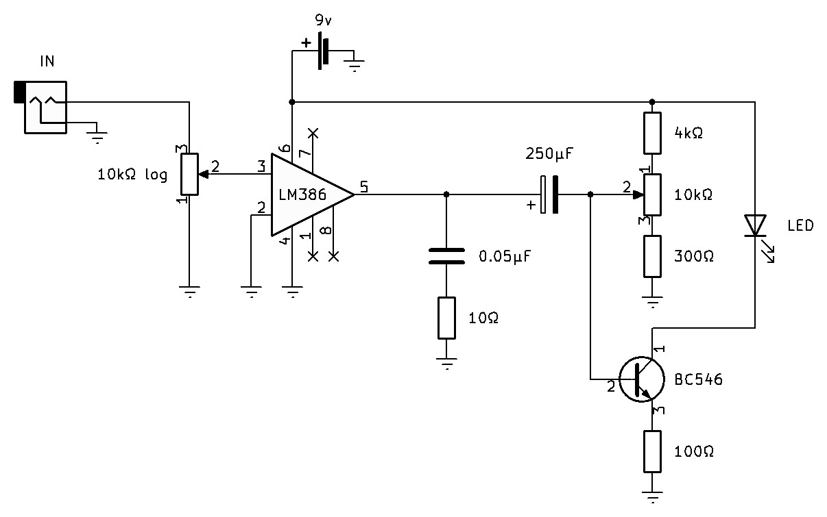
The electronic consist of a media player (cell phone, mp3 player...) connected to an LM386 amplifier and a simple LED driver circuit that drives the 5mm white LED in the lamp.
The amplifier is wired to have a gain of 200 and an input level potentiometer. The schematics can be found on page 10 of the LM386 datasheet.
The “driver” is basically an NPN transistor (BC546, 2N2222, or simmilar) with the output of the amplifier wired to the base of the transistor, an LED at its emmiter and ground at the collector. The potentiometer is wired as a voltage divider to regulate the brightness of the LED. A lot of simmilar schemmatics can be found if you google “sound modulated LED” (this one was used as a reference).
next: Darkroom setup and recording
back to the project page