LIGHT/SOUND
inverting the function of a 16mm film projector and turning it into a recording device.
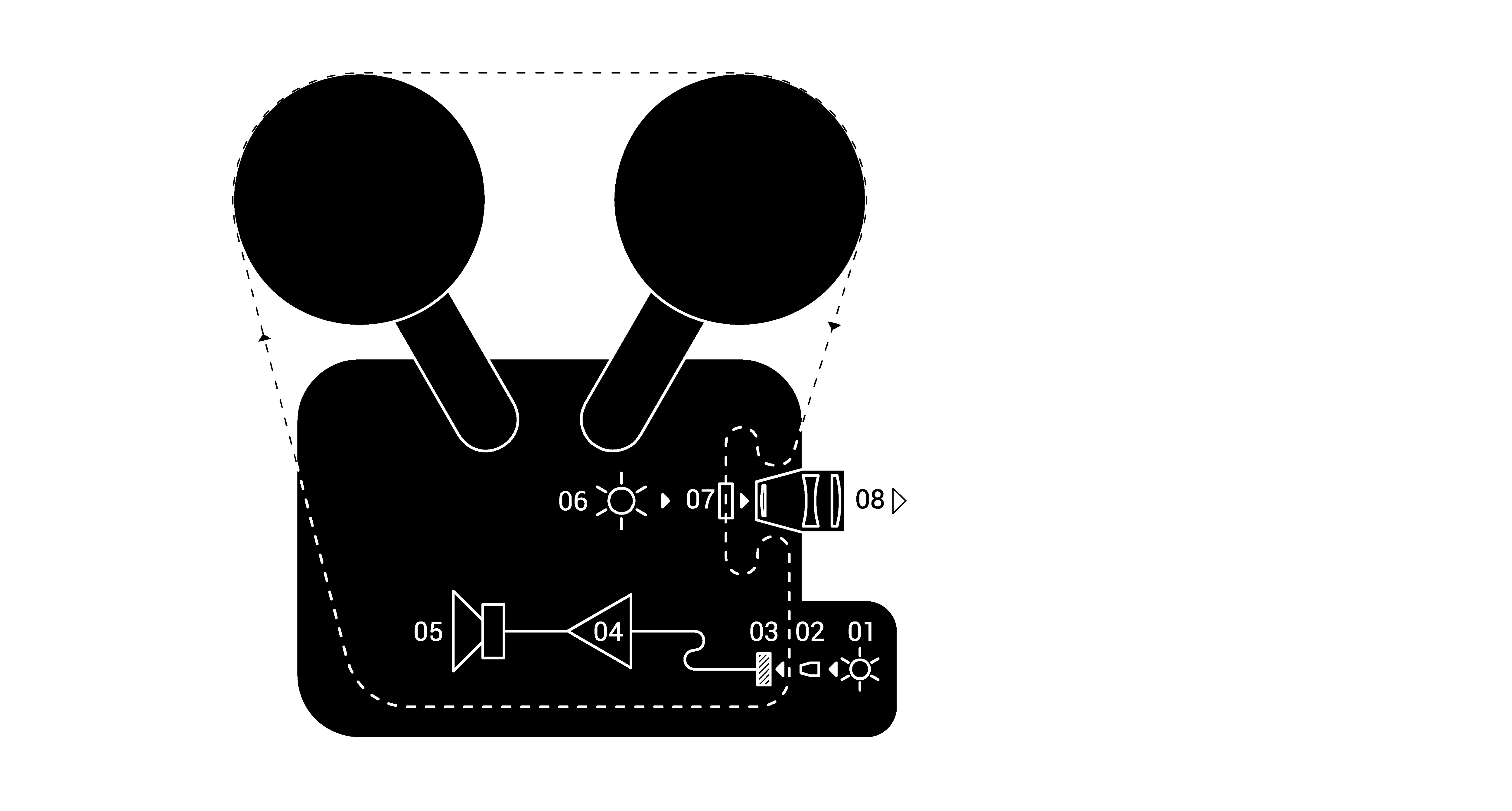
16mm sound film projector: 01: exciter lamp | 02: soundhead slit | 03: photo diode | 04: audio amplifier | 05: speaker | 06: projection lamp | 07: film gate | 08: lens
sound reproduction:
light (1) passing through a narrow slit (2) in the soundhead is focused onto the film soundtrack, where a varying proportion is transmitted, depending on the density and thickness of the lines on the soundtrack.
the flickering light is picked up by the photo diode (03) and converted into fluctuations in electrical current. this current fluctuations are amplified by the audio amplifier (4) and reproduced as sound waves by the speaker (05).
image reproduction:
film is passing frame-by-frame through the film gate (7) in front of the projector lamp (06). the image frame is projected through the projector lens (8).

modified projector/recorder: 01: sound source | 02: audio amplifier | 03: led driver | 04a, 04b: led | 05: soundhead slit | 06: image slit | 07: film gate
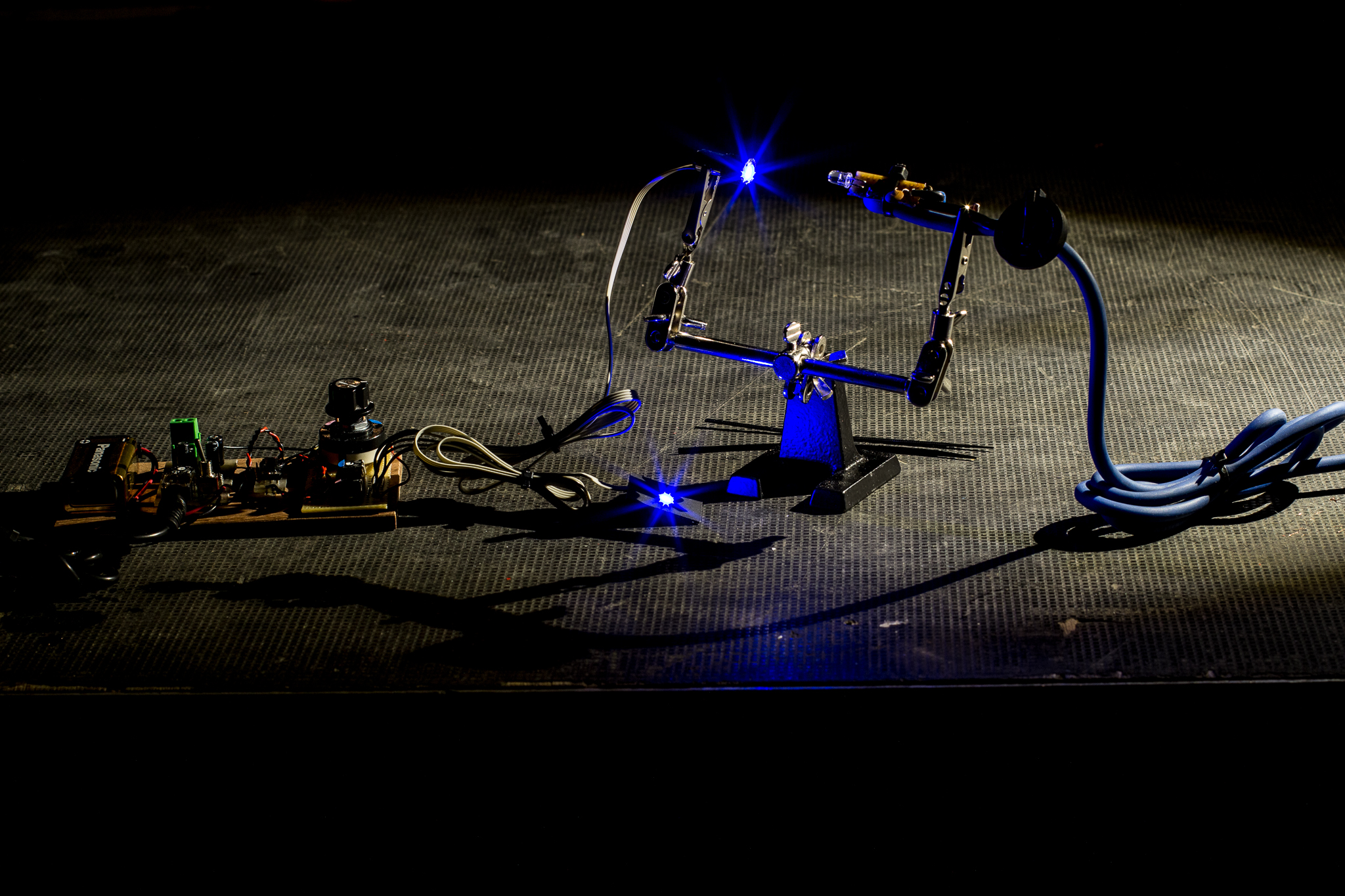
recording the sound.
pre-recorded sound on a device such as an mp3 player (1) is amplified with an audio amplifier (2). instead of a speaker, an led driver (3) and a pair of white leds (4a, 4b) are connected to the amplifier output. in this way, the led flicker is modulated by the sound source.
the first led is placed in front of the slit (05) in the projector sound head instead of the exciter lamp. the second led (4b) is placed behind the shutter instead of the projector lamp. a masking slit (6) is added to produce the visible line in the picture frame.
in the darkroom, unexposed film is fed through the projector. the sound source and the amplifier are turned on. as the film keeps moving in front of the flickering light source, the fluctuations are recorded onto film as a set of lines varying in density.
line density variations correspond to the pressure variations in the original sound wave from the sound source.
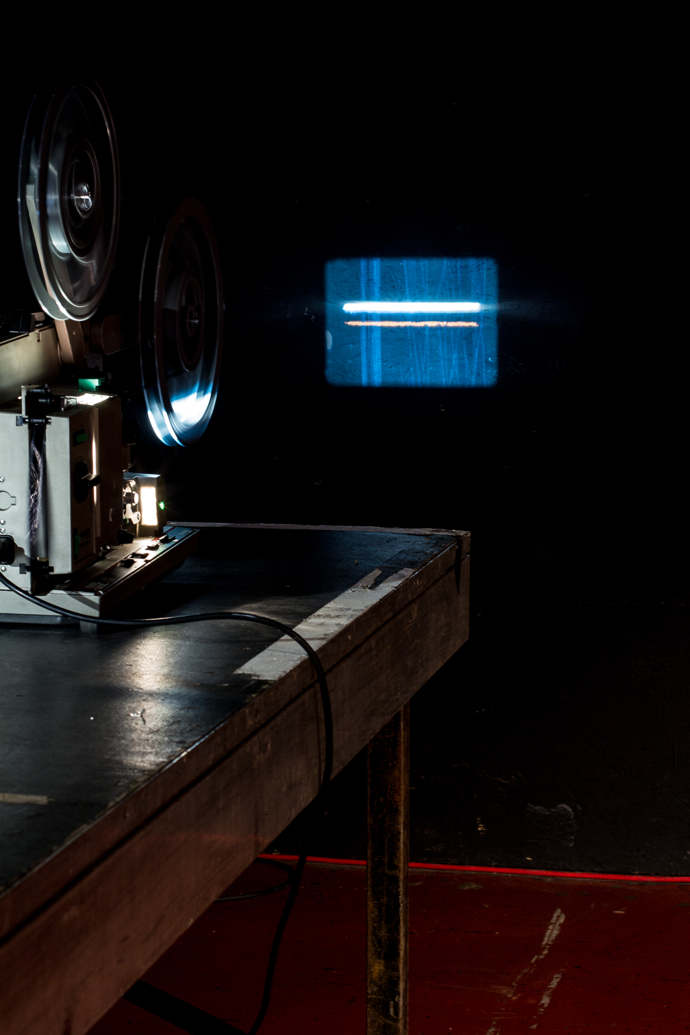
recording the image.
the flickering light from the led (4b) is projected onto the image frame of the film as it is passing frame-by-frame through the film gate (07).color variations.
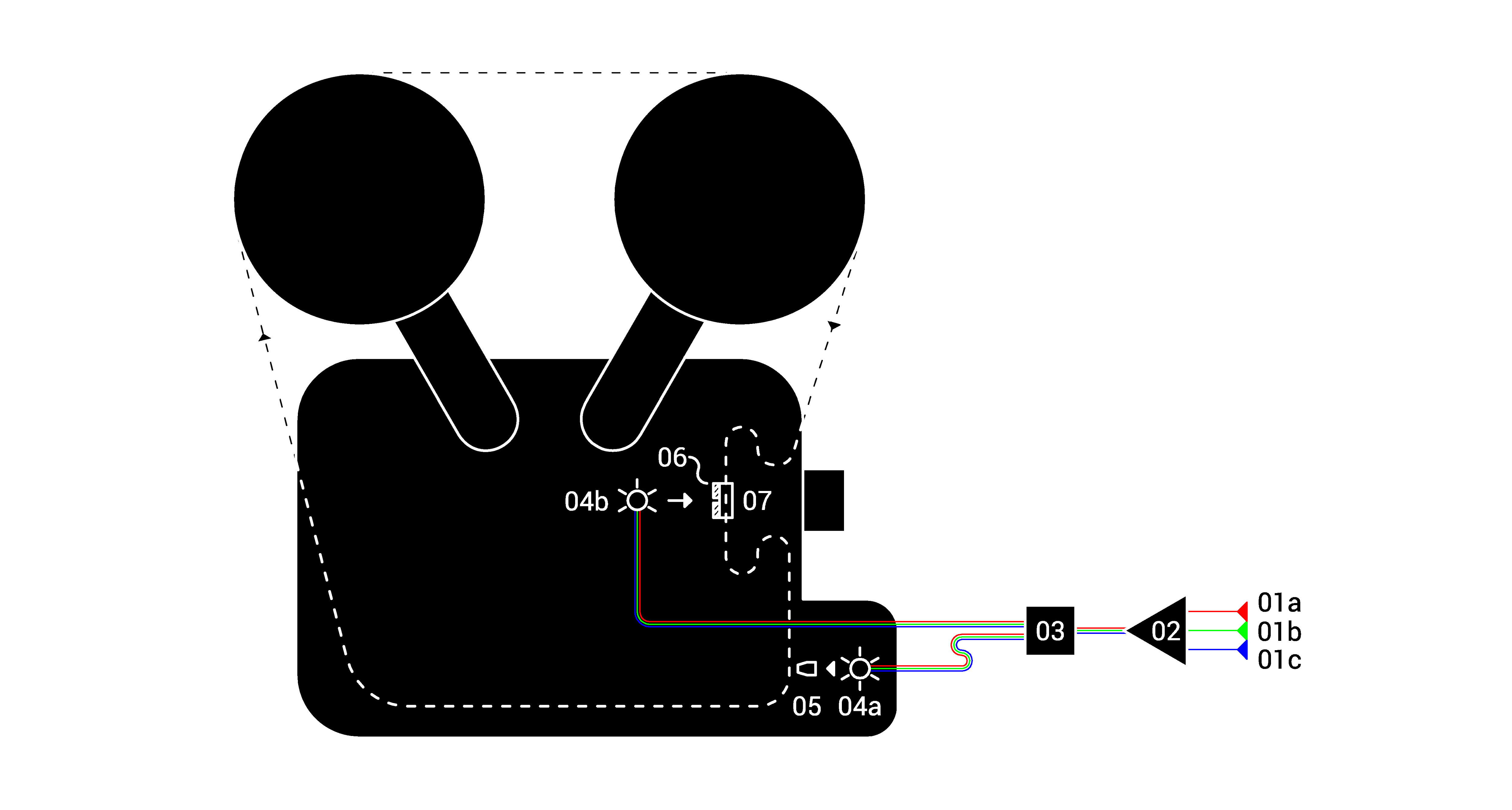
01a, 01b, 01c: sound sources | 02: audio amplifier | 03: led driver | 04a, 04b: led | 05: sound head slit | 06: image slit | 07: film gate
using color reversal film allowes for a slight modification of the procces: by using rgb leds (04a, 04b), three separate signals (01a, 01b, 01c) can be fed simultaniusly to the projector/recorder.
the result is a color soundtrack and image. each signal coresponds to one color. if signal frequencyes interfere constructively, lines overlap and produce new colors (for example: red and blue produce magenta).
since each signal is "color coded", they can be separated and isolated in reproduction by using optical color filters in front of the exciter lamp.
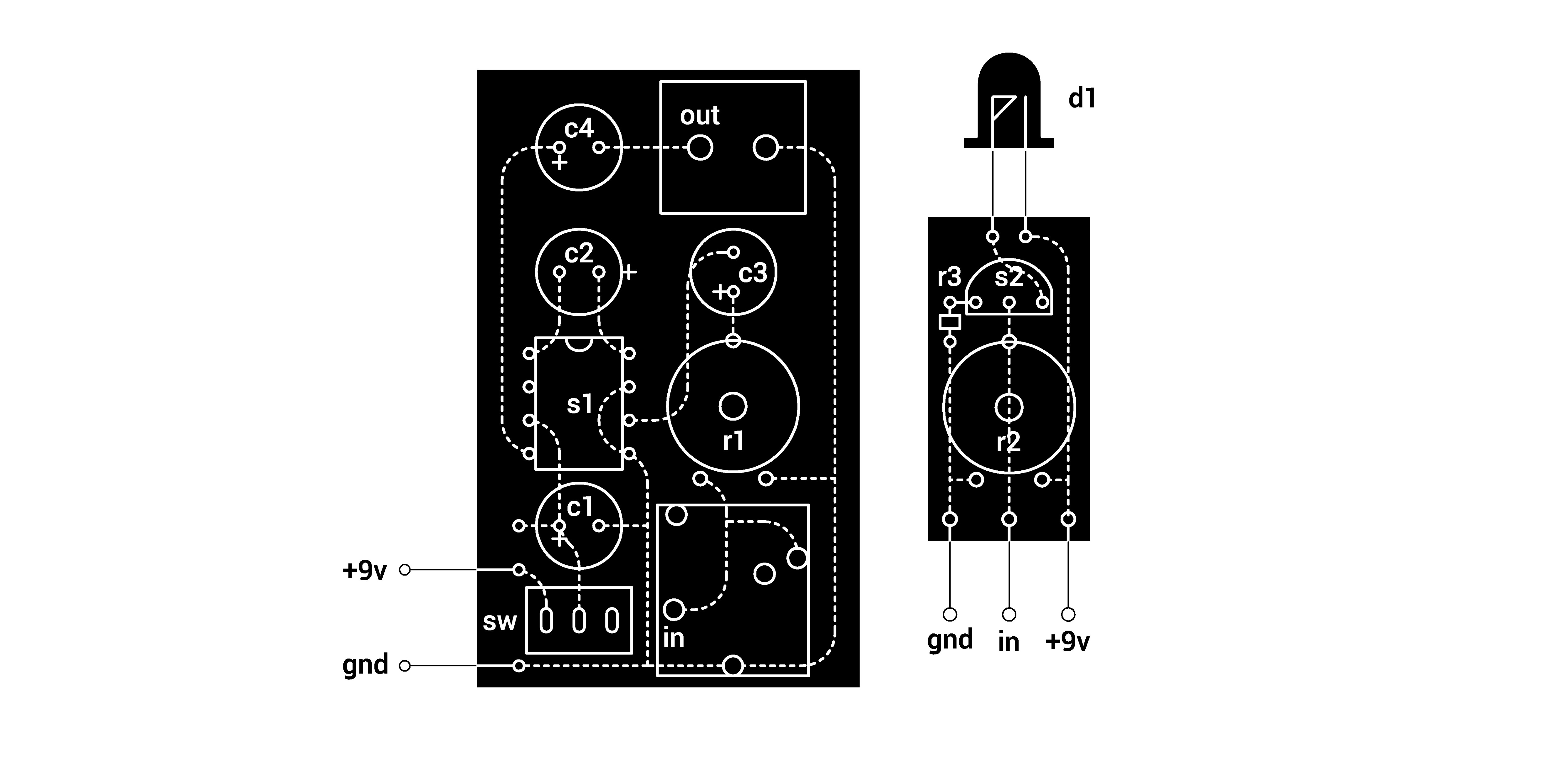
schematics for the printed circuit boards. left: audio amplifier. right: led driver: r1: 10k timpot | r2: 5k trimpot | r3: 100ohm | c1: 1uF | c2: 10uF | c3: 10uF | c4: 100uF | s1: lm386 | s2: bc546 | d1: white led | sw: spdt switch
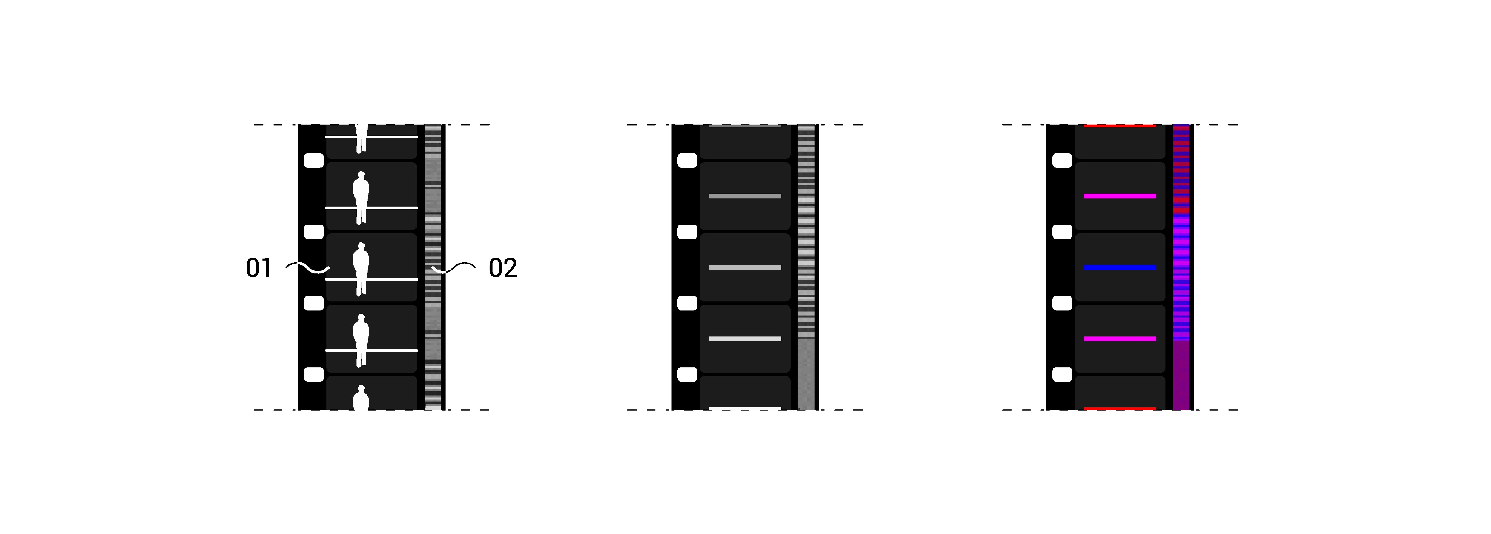
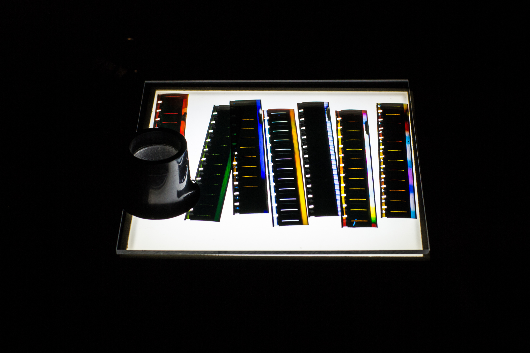
left: regular 16mm film. center: film recorded with white led method. right: film recorded with rgb led method 01: image frame | 02: sound track.
project featured as an installation in "sound art incubator" exhibition, june 2017, zagreb:
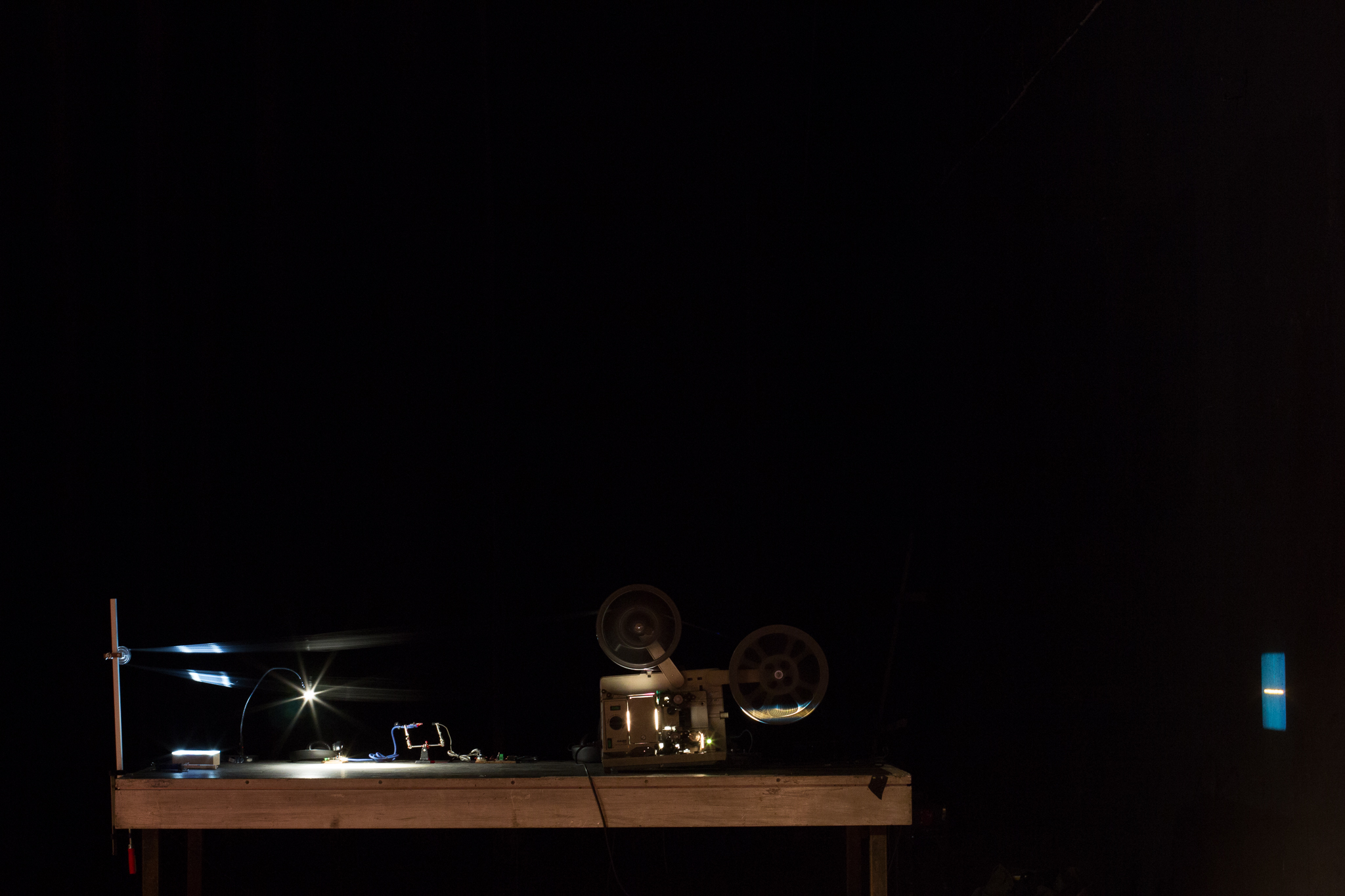
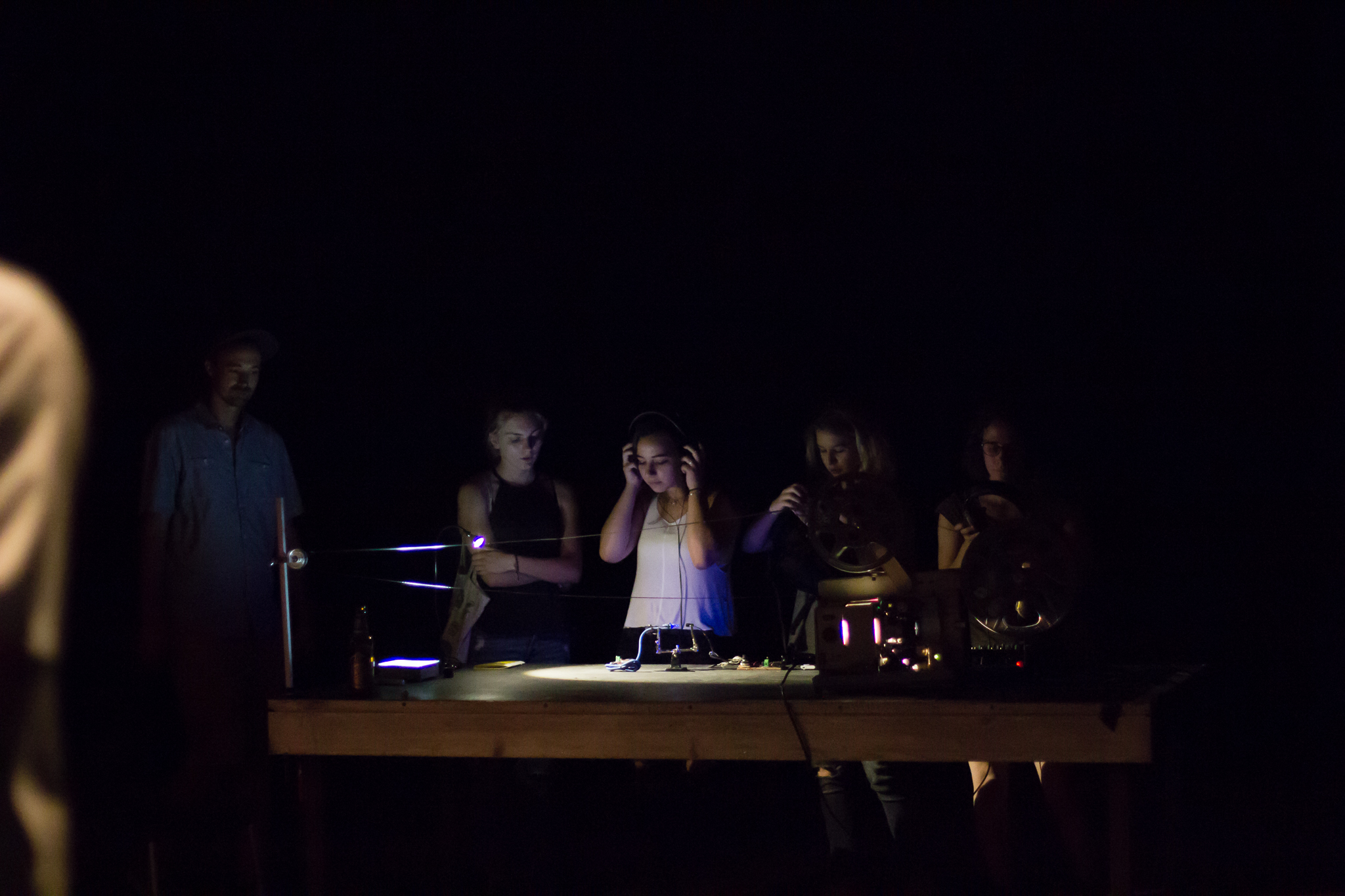
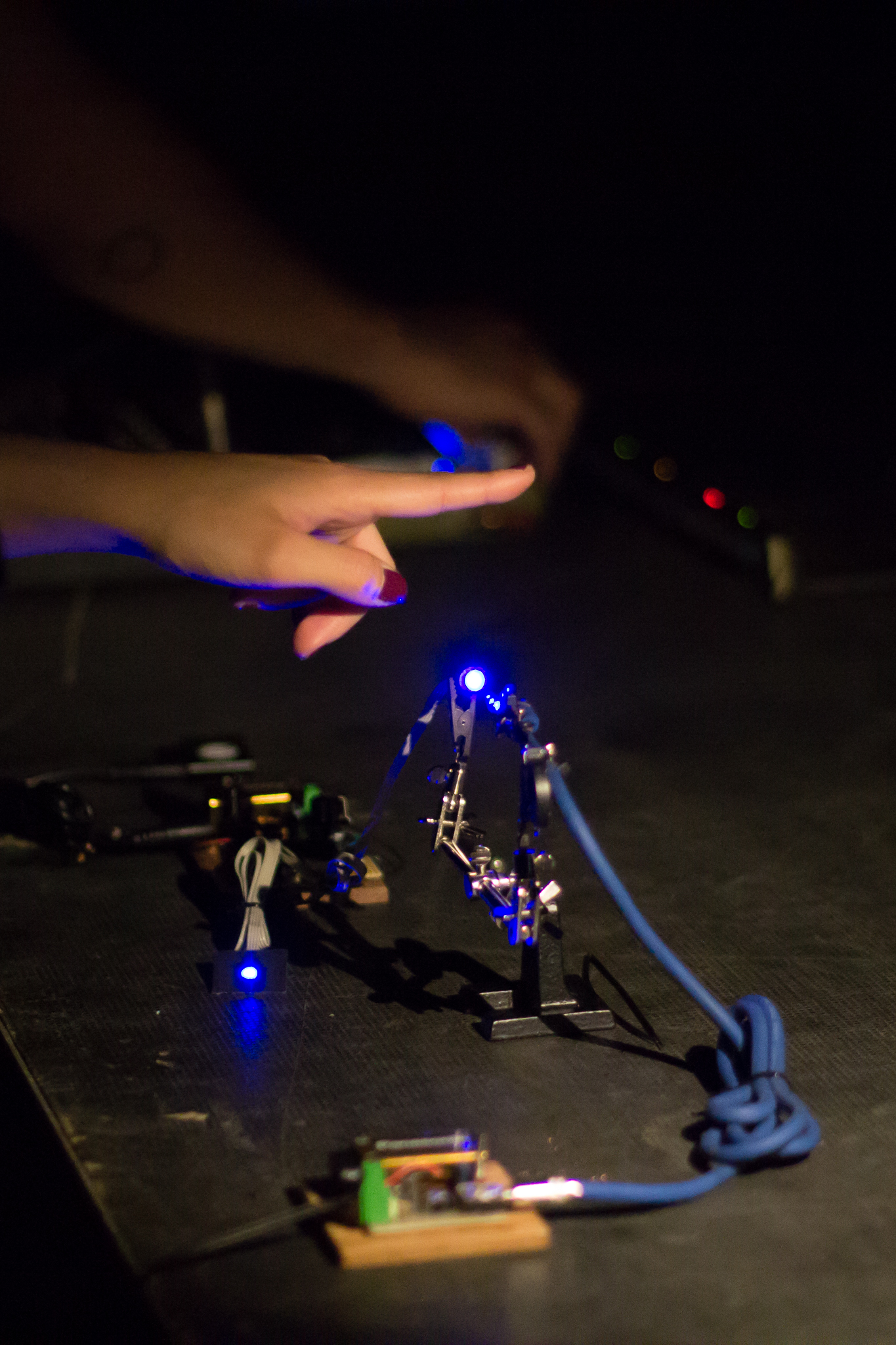

photos: katarina zlatec.